Project overview - Summer, 2005.
M.I.T. - CSAIL Humanoid Robotic Group
Adam Kumpf - Aug. 26, 2005
(with guidance and advice from Aaron Edsinger)
Supervised by Una-May O'Reilly and Rodney Brooks
Contents : |
Design Approach ^contents^
Observe, Brainstorm, Prototype, repeat... I believe these 3 steps are a great way to explore the new and useful devices of tomorrow.
This process was used over and over again as almost every prototype was pushed to the point of failure, observed for its weaknesses,
and questioned for ways to fix them between each revision.
 A few prototypes from this summer Each one helped me explore the design space. |
Initial Explorations ^contents^
Within the first few days of talking to people and getting setup with the Humanoid Robotics Group, a couple brainstorming lists
were made to think about new ways of grasping and manipulating objects. Below you will find a rough outline of the thoughts that were being considered.
|
Fiber Optic Force Sensing ^contents^
Compliant Manufacturing Techniques ^contents^
SDM, or Shape Deposition Manufacturing, is a technique currently being explored by many robotic laboratories as a method
to produce rigid and flexible parts that are cast as one mono-body and machined between each casting to produce a desired
shape and structure. A lot of useful information can be found on Stanford's SDM
Page. Instead of pin joints, flexures are used to eliminate gears and bearings. Unlike intricate mechanical
designs, SDM can be scaled very quickly if multiple parts are desired and most flexible cast structures bend, rather than break, if they are
twisted or pushed in an unintended way. A basic flexure design Notice the overlap between materials to aid in bonding and support. There are 3 parts to Shape Deposition Manufacturing:
In the case of my manipulator design, I did not repeat these steps for multiple layers of casting because I only used soft materials which are extremely tough to machine. Note: Always wear safety goggles, gloves, and other protective clothing when handling polyurethanes. Do not put unmixed polyurethanes in public spaces as they can be hazardous before cured. I kept all towels, mixing bins, stirrers, etc. in their own trash container and always wiped down the workspace when done. Wash your hands when you are done for good measure as well. For a short while, Planer castings were thought to be a potentially fast way to do shape deposition manufacturing. In particular, use of a laser-cutter, sheet acrylic, and sheet polyurethane were used as a starting block. Cuts were made to create a planer mold, flexible polyurethanes were cast, the surface was machined smooth and the laser-cutter was used again to cut the entire part. This method created some very complex and unique mono-body flexure designs in record time, but was only tried for about a week as the larger project design goal was pursued. For completeness, I have included my notes on the extremely rapid SDM technique using a laser-cutter and fast curing polyurethanes.  My notes on a Laser-Cutting SDM technique To make the fingertips of my hand, I first used a ball-end-mill to make 5 rounded pockets in a piece of aluminum. This was used as the mold. A secondary piece of aluminum was cut as a support structure for the fingers to keep them from touching the bottom of the mold. A soft two-part polyurethane (Shore 25A) compound was mixed, placed in the vacuum chamber to get rid of bubbles, poured into the mold, and then placed into the vacuum chamber once more to pull out any new bubbles that may have been created during the pour. Note that the first time polyurethane is placed in the vacuum chamber after mixing, it will increase in volume be a factor of 3-4 for a short time so make sure your container is large enough!  Casting the fingertips in a machined piece of aluminum. (25A Polyurethane - very soft) The flexible palm of the hand was also cast from soft 25A Polyurethane, but a black pigment was added for color. Since machining curved 3D shapes to be used as a mold can be very difficult and time consuming, a much simpler approach involving modeling clay was used. A basic palm was first constructed by pressing my own hand into the clay. It was then scaled down to the fit the Elacoil actuators and dummy actuators were placed to create pockets for the Elacoil structures. I built a very high lip around the palm so that after the polyurethane was mixed I could pour it directly into the mold, leaving the necessary 3-4 times additional volume when initially placed in the vacuum. The clay worked very well, but I should have taken more time to make it smooth. Every little detail will be transfered to the cast piece so take care when creating your mold.  Clay mold formed. Ready to cast.  Mold filled with soft 25A Polyurethane. (black pigment added)  Holding the palm fresh out of the mold. (view is from the back) The Elacoil actuators have been inserted into the slots left by the dummy actuators.  The final flexible palm, with Elacoil actuators. (view is from the front) |
Fluid Actuation Methods ^contents^
|
Creating a hydraulic system from scratch is quite difficult. Tolerances must be kept very close and seals work
differently at different pressures. Two thousandth's of an inch can mean the difference between a smooth stroke
and a stuck piston. If you go two thousandths the other way, the seal will allow blow-by, a form of leakage under
pressure. After a few initial tries in the shop, we were convinced that it was worth the money to buy pistons instead of making them. But money does not buy everything, and before long we realized that small low pressure pistons were not easy to come by. We tried using some nice pneumatic pistons for low pressure hydraulcs but found that air bubbles started to appear after minimal use. However, we did make a test rig to examine force and position feedback. It was intersting to see how the dynamics of the system changed as more air leaked into the lines. The output went from a solid push-rod to a springy slider as time progressed. Video of Position Feedback with low pressure hydraulics The smallest form of an everyday hydraulic apparatus I could find was a syringe. With sizes down to 3cc easily obtainable, syringes made for a very nice, inexpensive starting point for the hybrid design. A new machined plunger was made to allow for a direct connection to a motor and a O-Ring was place around the plunger to provide the necessary seal. This syringe with modified plunger design was used to drive the low-pressure hydraulic system. Hydraulic lines work extremely well when they are void of air. However, it is not so easy to seal the tubing without letting some air bubbles sneak in. To combat this, I highly recommend the use of a bleeder valve or some other easily accessible port that will allow you to cleanly fill and seal your hydraulic lines. I found that a pipe-threaded cap and a nylon barbed tube fitting did the trick rather nicely. Just be careful not to damage the small fittings or you may crack the nylon and create small leaks.  Rubber gaskets and a pipe-thread cap used for bleeding the low pressure hydraulic lines. It became quite clear early on that sliding parts in a hydraulic system are their weakest link. If diaphragms or balloons are used, containing the fluid is rather simple and there are almost no frictional losses. However, the challenge then becomes how do you get useful work from the flexible structure's change in size, shape, and pressure? One common method for extracting useful work from an expanding flexible structure is to place it inside a cross-woven sheath that inherently shortens as it grows in diameter. This is known as a McKibben Muscle and has been used on robotic projects such as the shadow hand. These have the ability to efficiently contract with a significant amount of force. But what about extension? It is often desired that parts of an actuated device be able to extend as well as contract. Users of McKibben muscles often put them in pairs around a hub to give rise to bidirectional actuation, but this is limited since causing a linear extension with McKibben muscles requires a significant amount of complexity and physical space. The challenge I posed to myself was to find a way to create an actuator that delivered useful work from an expanding flexible structure (i.e. latex tubing) in the extension mode. I started by constraining the balloon like structure in a brass pipe, but soon found that very little force was exerted in the direction normal to the tube's planer cross section. It seemed as though the balloon (latex tubing) pushed hard into the side wall of the outer pipe and produced significant friction. I tried greasing and oiling the brass pipe, but results were similarly negative and somewhat variable. I kept looking for some sort of miniature bellows like material to use, but could not find anything in a reasonable price range. The Elacoil (Elongation Actuator Coil) The more I starting to think on a tangent about spring returns for McKibben muscles, the more I began to realize that the spring may be more useful than that to the "balloon in a pipe" problem. I asked myself, "what if the sidewalls of the pipe could elongate after the balloon had pressed up against them?" The spring did exactly that. By placing a piece of flexible latex tubing down the center of a 1/4" O.D. light-duty extension spring, pressure applied to the latex tubing pushed the sidewalls of the latex into the inner walls of the spring and then proceeded to elongate the spring as more pressure was applied. I'll refer this "latex tube constrained by a spring" as an Elacoil, or Elongation Actuator Coil. It was quite amazing and strange!  Video of an Elacoil (latex tube constrained by a spring) Next, the challenge was to place this newfound actuation method into a finger, hopefully causing it to bend. It should be noted that elongating the Elacoil too far can allow for the latex tubing to push through the coils of the spring and potentially rupture. Since you "can't push on a rope" without heavily constraining it, making the Elacoil bend a finger took some serious thought. Eventually, I found that starting with a fully constraining chassis and modifying it to give rise to the degrees of freedom I desired was the easiest way to get the Elacoil to move and bend as I planned. Below is one of the first fingers created with the Elacoil. Notice the larger outer tube used to constrain the spring and the notches around the knuckle to allow the joint to bend. 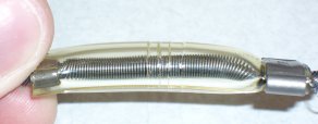  Video of an Elacoil actuated finger For completeness, I have included a step-by step guide on how to make an Elacoil (Extension Actuator Coil). I encourage others to try new materials and methods since I have only been experimenting with Elacoils for a couple months.
|
The Final Result ^contents^
The final design for my summer exploration in the field of compliant robotic manipulators was decided upon by combining as many of the most promising and novel concepts explored as possible. It would have been nice to include a fiber optic force sensor, but time constraints and a lack of strong experimentation with that idea kept it from appearing in the final design. The implemented final design focused on the following aspects:
Each finger was constructed as described in the step-by-step guide above. This produced five fingers 3/8" in diameter, ~2.5" long, and each containing an Elaocoil extension actuator. This is roughly the size of the human finger at its narrowest regions and provided the dominant degrees of freedom found in the human hand. An extra degree of freedom would have been nice to make up the finger-tip joint in each finger, but the knuckle and the mid-joint of each finger seemed sufficient at its current stage of development to demonstrate the idea. All of the fingers were then setup in an aluminum frame to cast fingertips upon them. The fingertips were cast out of a very soft Shore 25A two-part polyurethane. Once cured, the fingers (with their new rubber tips) were removed and set aside. The next step was to cast the palm of the hand. Dummy Elacoils (simply the tubing and a hose crimp) were used to make pockets for the real actuators. The palm was also cast from a soft 25A polyurethane with the addition of a little black pigment for color. The mold was created by hand out of modeling clay and took less than an hour to set up. After the palm had hardened, the dummy Elacoils were removed and the real ones inserted in their place. A McKibben muscle was also placed across the palm to allow it to flex inward. It was attached to the soft palm with a piece wire, a couple hose crimps, and a washer. With the five-fingered hand, cast fingertips, and a flexible palm, the focus shifted towards making the hydraulic actuators. A set of four motors, machined plungers, syringe sleeves, and bleeding valves were assembled to allow for the hydraulics to be individually controlled by a switch box and a power supply.  Switch box to control the motorized hydraulic actuators  Syringes mounted with bleeding valves Each line was bled by placing the entire apparatus in a vacuum chamber and adding water as necessary via a simple syringe-like reservoir. Use of the vacuum chamber greatly aided in the ability to remove air from the hydraulic lines of the system.  Drawing of the motor driven syringe device  Drawing of the custom syringe plunger
The final design is compliant, uses cast structural components, is life-like in shape and size, uses small scale hydraulic actuation, and nicely showcases the potentially novel Elacoil actuator. 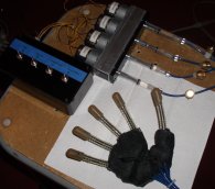 Video of final design More Video Even More Video  Closeup of the hand
|

